 Inside the Asset
Illustrative inspection scene. The numbered anatomy reference below locates common components and inspection zones; actual equipment configurations vary.
What it is
A large, low-pressure (essentially atmospheric) vessel that stores liquid product — crude, refined fuels, chemicals, water. Built as welded steel shells on a foundation, with a bottom plate, cylindrical shell courses, and a roof.
This guide focuses on welded, aboveground steel tanks in essentially atmospheric service. Fixed-roof and floating-roof arrangements have different inspection needs. Begin with the tank drawing and service history so the floor, shell, roof and foundation are assessed as one containment system.
How it works
Shell. Welded plate courses contain the stored liquid. Liquid pressure increases with depth, which is why lower courses commonly require greater thickness. Course numbers and elevations give shell readings a repeatable location.
Bottom and shell edge. Bottom plates separate product from the foundation and can corrode from either side. An annular plate, where fitted, forms part of the highly loaded perimeter. The shell-to-bottom connection needs its own examination coverage.
Roof and vapor space. A fixed roof encloses the vapor space. A floating roof follows the liquid level to reduce exposed liquid surface; seals, pontoons and drains introduce additional components to inspect.
Connections and foundation. Nozzles, manways, vents and mixers provide access and operating functions. The foundation supports the tank, while drainage and settlement affect the condition of the floor and shell.
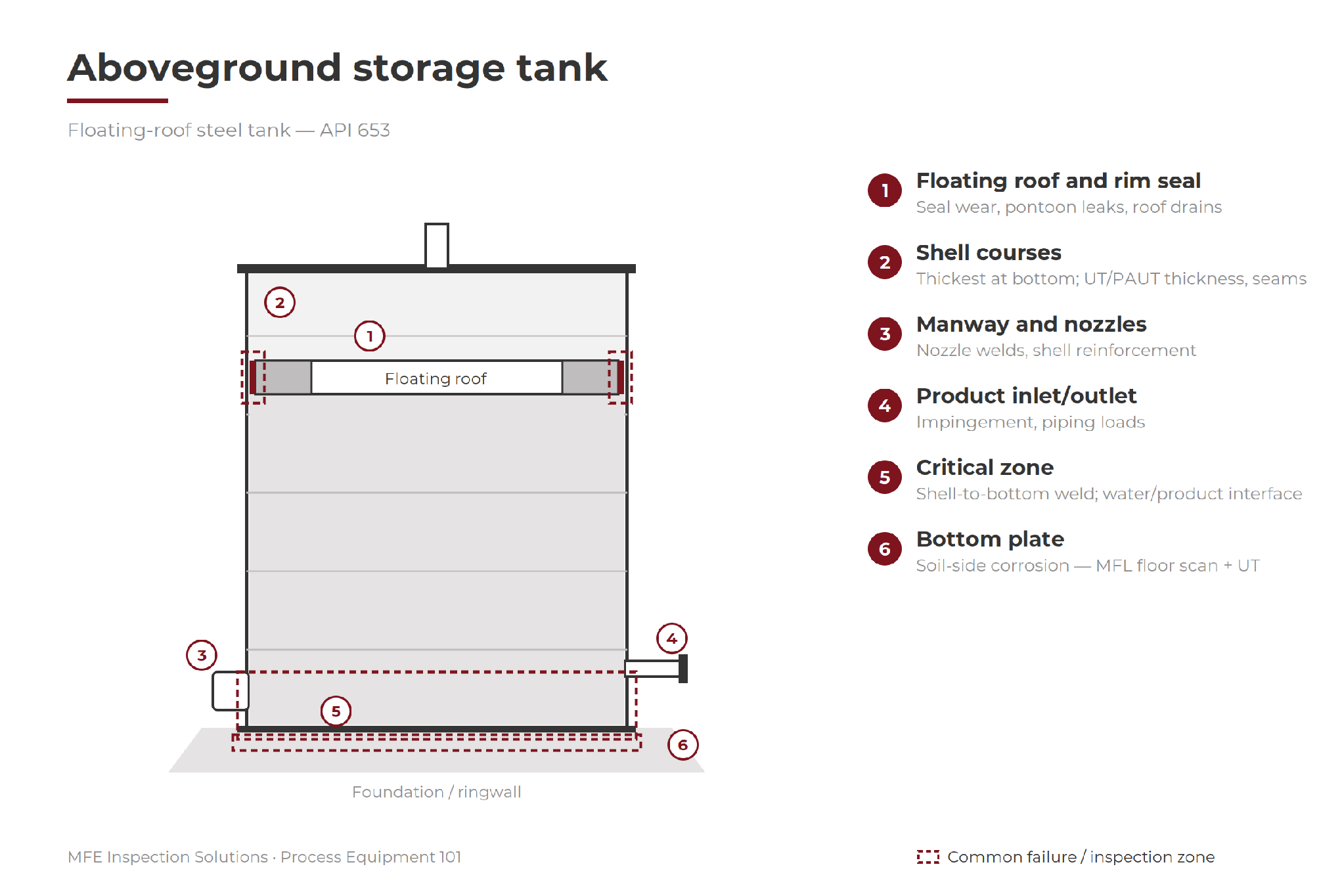
Original numbered component and inspection-zone illustration. Use the tank’s own plate and nozzle drawings to localize findings; diagram labels are inspection prompts, not acceptance criteria.
Where it fails
Floor plates. Soil-side corrosion can remain hidden beneath an apparently sound upper surface. Product-side corrosion, pits and low points also need attention; location and extent matter when planning confirmation and repairs.
Shell-to-bottom edge. Corner corrosion and cracking can threaten containment in an area that a full-size floor scanner cannot completely cover. Record the perimeter separately from the open floor.
Lower shell and water interface. Accumulated water and service chemistry can concentrate corrosion near the bottom or along a liquid interface. Isolated spot readings may not describe the full extent of local damage.
Floating-roof components. Worn seals, leaking pontoons and damaged drains can affect emissions control, buoyancy or rainwater removal. These components require functional and condition checks suited to the roof design.
Foundation and geometry. Uneven settlement can distort the shell and load connections. Survey data, visible foundation condition and prior measurements help determine whether further engineering assessment is needed.
How it gets inspected
Treat the floor, shell, roof and foundation as related inspection scopes. Plan floor screening and indication confirmation together, then record edge zones and other areas the scanner cannot cover. The route should connect findings to their physical locations and the follow-up needed before return-to-service decisions.
API 653 addresses inspection, repair, alteration and reconstruction of applicable aboveground storage tanks. The tank design, service, jurisdiction and owner’s inspection program determine the governing requirements. [1]
Equipment for the job
Select the method for the suspected damage, material, geometry and access, then choose a suitable instrument and configuration. These equipment examples support different parts of the job; no single tool establishes the condition of the entire asset.
Bottom plate (MFL). MFE Mark IV Tank Floor Scanner for the floor; MFE Edge / 1212 Mark II EdgeScan for the critical zone; HandScan for sumps and under nozzles; UT prove-up with the Olympus 38DL Plus
Shell thickness and seams. Cygnus 1 Ex for compatible hazardous-area duties; OmniScan X4 for targeted PAUT weld examination; MFE HPX Wall Crawler for accessible ferromagnetic shell surfaces at height.
Critical zone weld. magnetic particle testing (MT) or penetrant testing (PT), selected for the material and inspection procedure, complements thickness measurements.
Internals (out of service). Flyability Elios 3 + UT Payload for remote visual inspection and accessible contact measurements; MFE TankMaster PTZ275 / PTZ550 for views through suitable openings. Remote access can reduce personnel entry, subject to isolation, atmosphere, access and site controls.
External shell and roof. DJI Matrice 350 RTK with a compatible Zenmuse H30-series payload for remote visual inspection; thermal imaging requires the H30T variant.
Floating-roof seals and vents. MFE Detect MW OGI Camera or a compatible MFE OGI 640 payload can support gas observations where the target gas matches the instrument’s spectral response. Viewing conditions and the roof arrangement affect detection; an image does not quantify every emission or replace roof-component checks.
Field note. A floor scan is only useful when indications can be relocated and confirmed. Keep scanner coverage, edge-zone coverage and confirmation results together on the same tank map.
Why it matters
A tank outage brings floor scanning, UT confirmation, shell assessment and remote access together. Plan the sequence early so screened indications can be confirmed before repair and return-to-service decisions.
Ask your inspection provider
How will you confirm floor indications and cover the shell-to-bottom edge before the tank returns to service?
Field card - record on every route
Identify. Tank ID, service, roof type, floor drawing, plate numbering and examination date.
Record. Plate and shell-course locations, method, instrument settings, surface condition and accessible coverage.
Confirm. Trace each screened indication to its UT or other appropriate follow-up result.
Flag gaps. Shell-to-bottom edge, obstacles, coated areas and any inaccessible floor or roof locations.
Close the loop. Findings, required follow-up, repair disposition, responsible person and return-to-service decision reference.
Support for the inspection
Arrange method-specific training, current calibration and a floor-access review before mobilization. Confirm the plate-numbering convention, edge-scanning plan and how repair findings will be returned to the tank record.
Training, Repairs & Calibrations and Proof of Concept support are available through MFE Inspection Solutions.
Sources and equipment references
1. API - Aboveground storage tank inspection
2. MFE - Mark IV tank floor MFL scanner
3. MFE - Edge-zone MFL scanning
4. Flyability - Elios 3 remote inspection platform
This educational guide does not replace an asset-specific inspection procedure. The author is an executive at MFE Inspection Solutions. Equipment and service links lead to MFE; cited manufacturer information supports method selection. Confirm instrument suitability and availability for the planned scope.