 Inside the Asset
Illustrative inspection scene. The numbered anatomy reference below locates common components and inspection zones; actual equipment configurations vary.
What it is
A closed container designed to hold gases or liquids at a pressure different from ambient. Separators, knockout drums, reactors, heat exchanger shells, accumulators and air receivers are examples. Many process vessels are designed and stamped to ASME Section VIII; the applicable construction code depends on the vessel and jurisdiction.
This guide uses a horizontal separator or knockout drum as the illustrated example. Reactors, receivers and other vessels may have different internals and damage mechanisms. The pressure boundary, supports, internals and pressure-relieving devices each need a defined scope.
How it works
Shell and heads. The shell forms the main pressure boundary, closed by shaped heads. Longitudinal seams, circumferential seams and head-to-shell connections provide distinct examination locations.
Nozzles and attachments. Reinforced openings connect process piping, instruments and relief devices. Nozzle necks, welds and attached piping must accommodate pressure, temperature and external loads.
Pressure relief. Relief devices protect against specified overpressure scenarios. Set pressure and relieving capacity are separate engineering checks against maximum allowable working pressure and the applicable code; the diagram’s abbreviated label is not a universal setting instruction.
Internals. Demisters, baffles, trays or catalyst supports perform the process duty. An internal component can fail and impair operation even when the outer pressure boundary remains intact.
Supports and insulation. Saddles or skirts transfer load to the foundation. Insulation controls temperature, but concealed surfaces and support contacts can make corrosion harder to find.
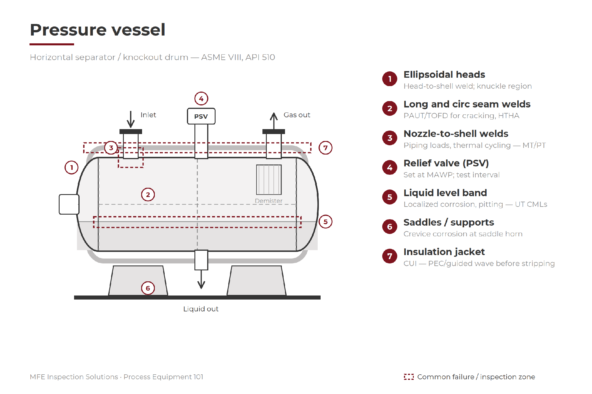
Original pressure-vessel location reference. Relief settings require an engineering check; HTHA requires a specialist examination strategy. Technique labels in the graphic do not establish suitability or complete coverage.
Where it fails
Shell, heads and liquid-level bands. General thinning, local pits and low-point corrosion depend on the fluid, deposits and operating history. Measurement locations should follow credible damage, not only the easiest access points.
Seams and heat-affected zones. Fatigue and environment-assisted cracking require examinations sensitive to the expected crack orientation and location. A thickness survey does not provide the same evidence as a crack examination.
Nozzle-to-shell connections. Piping loads, vibration and thermal cycling can concentrate stress around the connection. Record the nozzle ID and exact weld location when reporting an indication.
Hydrogen-related damage. Susceptible service can create different forms of hydrogen damage. High-temperature hydrogen attack requires specialist procedures and interpretation; ordinary weld scanning cannot establish its absence. [2]
Insulated surfaces and supports. Water ingress beneath insulation and crevices at supports can conceal deterioration. Thermal anomalies may guide follow-up, but they do not confirm corrosion or establish remaining thickness. [3]
How it gets inspected
Start with service history and credible damage mechanisms, then select examination locations and methods. Separate containment assessment from inspection of internals. Record areas remote tools can reach, areas they cannot, and the additional examinations needed to support engineering decisions.
API 510 provides an in-service framework for applicable pressure vessels, including inspection and repair activities. The construction code, service and jurisdiction still govern the asset-specific assessment. [1]
Equipment for the job
Select the method for the suspected damage, material, geometry and access, then choose a suitable instrument and configuration. These equipment examples support different parts of the job; no single tool establishes the condition of the entire asset.
Shell and head thickness. Olympus 38DL Plus, 45MG, Cygnus 1 Ex; Olympus HydroFORM for corrosion mapping on the liquid level band
Welds (PAUT/TOFD). OmniScan X4 / X3 with suitable probes and COBRA or ChainSCANNER where geometry permits; Eddyfi Sharck for compatible surface-crack examinations. HTHA requires a specialist, validated examination strategy; a standard weld scan does not establish its absence.
Nozzle welds and SCC. MT, wet fluorescent MT or PT as appropriate to material and the expected surface-breaking damage; examination coverage follows the procedure.
CUI screening. MFE PulsePro or Eddyfi Lyft pulsed eddy current on compatible ferromagnetic walls through suitable insulation systems; FLIR T540 can help identify thermal anomalies for follow-up. PEC averages thickness over a footprint, and thermography alone does not confirm corrosion.
Internals at turnaround. Flyability Elios 3 + UT Payload can reduce scaffolding and personnel entry; Evident IPLEX GT reaches suitable nozzles and small openings. Site permits, isolation and atmosphere controls still apply.
Materials verification. XRF / PMI / LIBS analyzers on repairs and replacement nozzles; Fischer Feritscope on stainless/duplex welds; Proceq Equotip 550 hardness after PWHT
Field note. Treat containment, internal condition and relief-device performance as related but distinct questions. State what each examination actually established and what remains outside its coverage.
Why it matters
A vessel inspection must address both pressure containment and the condition of its internals. A realistic access plan can reduce turnaround disruption while preserving the coverage needed for engineering decisions.
Ask your inspection provider
Which damage mechanisms drive the examination, and what areas will remote inspection leave unexamined?
Field card - record on every route
Identify. Vessel ID, service, material, design references, inspection history and expected damage mechanisms.
Record. Shell/head/nozzle locations, examination technique, instrument configuration and measured findings.
Confirm. Document how significant indications will be characterized; identify any specialist HTHA scope separately.
Flag gaps. Internals, supports, insulation-covered areas and remote-access limitations.
Close the loop. Engineering review, follow-up examinations, repair decisions and responsible person.
Support for the inspection
Review the expected damage mechanisms, access openings and weld geometry with the inspection provider. Arrange specialist support where hydrogen damage is credible, and connect significant findings to engineering review before disposition.
Training, Repairs & Calibrations and Proof of Concept support are available through MFE Inspection Solutions.
Sources and equipment references
1. API - Pressure vessel inspection framework
2. Evident - Dedicated HTHA examination strategy
3. Eddyfi - Pulsed eddy current and probe footprint
4. Flyability - Elios 3 remote inspection platform
This educational guide does not replace an asset-specific inspection procedure. The author is an executive at MFE Inspection Solutions. Equipment and service links lead to MFE; cited manufacturer information supports method selection. Confirm instrument suitability and availability for the planned scope.