 Inside the Asset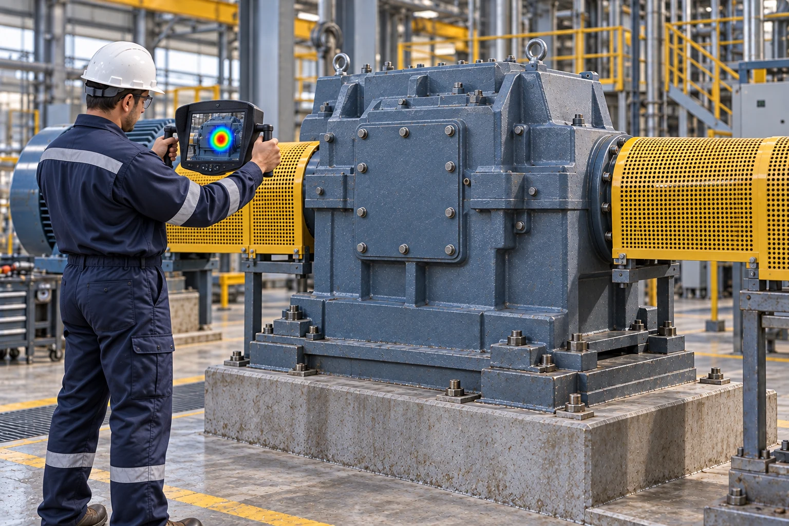
Noncontact acoustic screening to localize sound around a closed gearbox; mechanical diagnosis requires corroborating evidence. AI-generated illustration; instrument appearance and geometry are illustrative.
What it is
An industrial gearbox transmits mechanical power between a driver and driven equipment. Gear ratios change speed and torque; some arrangements also change shaft direction. Pumps, mixers, conveyors and other plant equipment use different gearbox designs to suit their duty.
This guide illustrates a parallel-shaft helical reduction gearbox. Planetary, bevel and high-speed turbo gear units require different component maps and analysis. Treat the complete train, operating load and supporting base as part of the investigation. [1]
How it works
Input and gear stages. The input shaft receives power from the driver. Meshing gears transfer load through one or more stages. The ratio and tooth counts help relate a vibration observation to the expected running and gear-mesh behavior.
Shafts and bearings. Bearings support the shafts and control their position. The arrangement determines where accessible measurements can be made and which internal surfaces a videoscope can reach.
Lubrication and seals. Splash or forced lubrication supplies the working surfaces according to the design. Oil condition, delivery and contamination control deserve attention alongside the visible teeth. Seals help retain lubricant and exclude contamination.
Housing and support. The housing maintains alignment of the internal components and provides access covers. Couplings, mounting feet and the foundation affect the complete drive-train condition. [1]
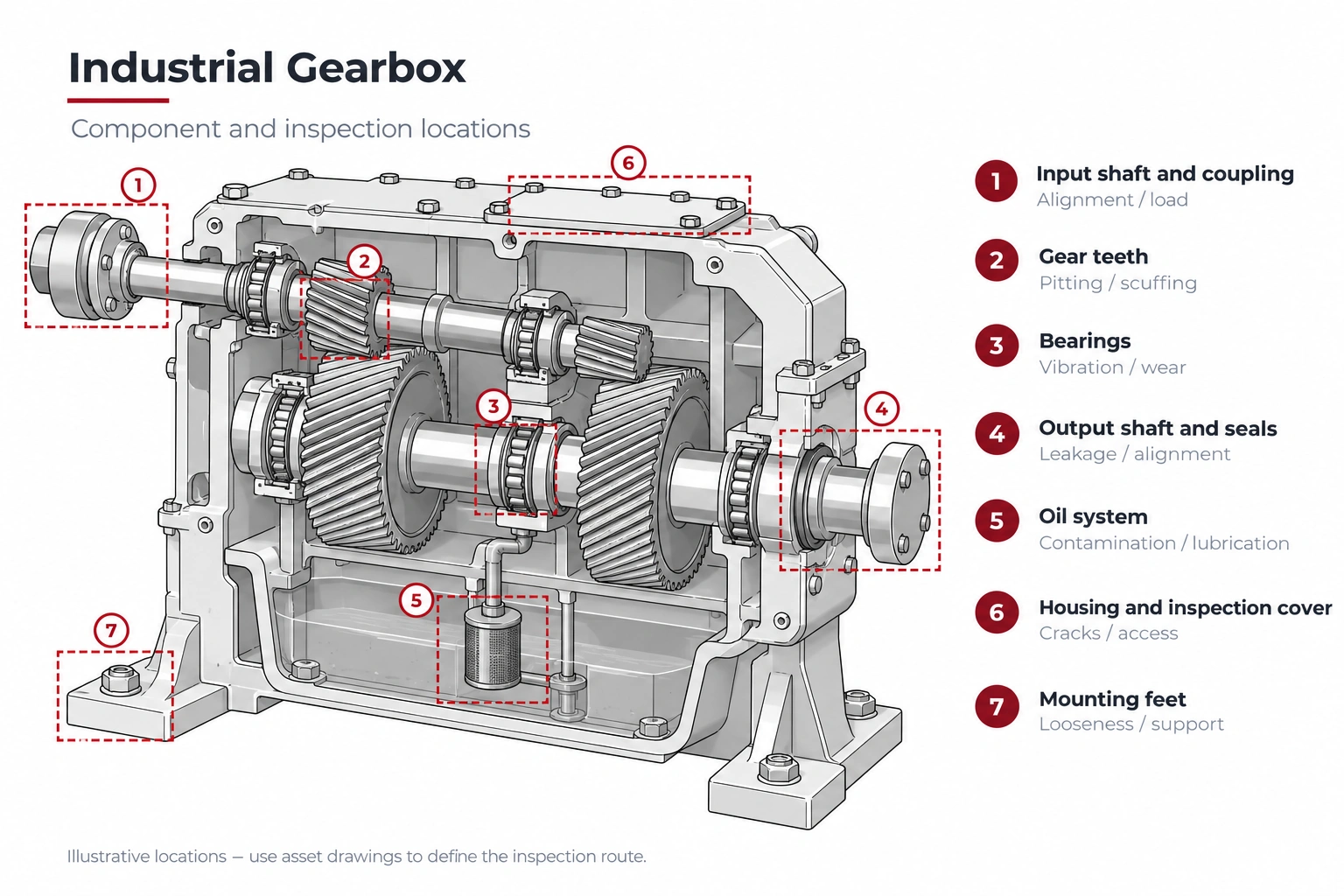
AI-generated component-location illustration, not to scale. Use the asset’s drawings and identifiers to localize findings; highlighted zones illustrate component areas and do not define complete examination coverage.
Where it fails
Gear teeth. Pitting, scuffing, wear or damaged teeth require localization by shaft, stage and tooth region. A single visible surface does not establish the condition of the entire gear or its opposite flank.
Bearings and shaft support. Changes in vibration, noise or temperature can indicate a problem, but several mechanisms can produce similar symptoms. The operating speed, load and measurement location are essential context. [2]
Lubrication and contamination. Oil condition and delivery influence the working surfaces. Sampling results, filter/debris observations and operating history should be interpreted together; one clean sample does not clear every internal component. [2]
Housing, seals and mountings. Leaks, cracks, looseness or alignment changes warrant follow-up. Noise radiated by a housing panel may identify where sound escapes, rather than the exact internal component producing it. [1, 3]
How it gets inspected
Start by identifying the design, ratio, shaft references and operating duty. Review previous vibration data, oil results, repairs and any change in speed or load. Decide whether the task is routine condition assessment or diagnosis of a specific symptom.
Combine operating measurements with visual/endoscopic examination and oil diagnostics when appropriate. The scope should state which gears and bearings were reached, how observations were compared, and what additional access is needed. Manufacturer-supported maintenance and specialist diagnosis can require different depths of examination. [1, 2]
Equipment for the job
Choose the method for the question, then the instrument and configuration for the asset. The following options address different parts of the inspection.
Vibration analysis. Use suitable sensors, an analyzer and a speed reference for the specific gearbox and question. Document position, direction and operating load. A specialist may evaluate gear-mesh behavior and bearing-related features, but an overall vibration value is not a complete diagnosis.
Acoustic imaging. A Sorama CAM iV64s can visualize sound sources during an on-site investigation. Use a repeatable position, frequency selection and operating condition to compare observations. Establish usefulness against a known baseline or confirmed fault; a sound map alone does not prove which internal tooth or bearing is damaged. [3]
Internal visual inspection. A suitable industrial videoscope can document reachable teeth, bearings and internal surfaces through prepared access. The machine must be stopped and secured under its inspection procedure. Record stage, flank, orientation and coverage; do not label a partly viewed gear fully examined. [1] An Evident IPLEX GT is an option for reachable internal surfaces.
Oil diagnostics. Use a repeatable sample location and the appropriate laboratory program. Record lubricant identity, oil hours, recent changes and sampling conditions. Correlate significant findings with the mechanical evidence rather than assigning a fault from one isolated test. [2]
Thermal and alignment checks. Thermal imaging may help compare accessible housings and lubrication auxiliaries. Appropriate alignment measurements can investigate the connected train during prepared access. Neither technique independently measures internal tooth condition; each should answer a defined question. A FLIR T540 can support the thermal portion of the assessment.
Direct measurements and targeted NDT. When indications or access justify it, specialists may use dimensional checks and suitable crack examinations. Gear geometry, surface condition and suspected mechanism determine the method. Inspection findings and OEM/engineering acceptance are separate steps.
Field note
Use acoustic imaging to localize and compare sound, then test the diagnosis with appropriate mechanical evidence. The result should be a supported finding, not an automatic fault label.
Why it matters
A gearbox can affect an entire production or utility train. Combining repeatable external measurements with internal evidence helps avoid both unnecessary teardown and unsupported reassurance. The value lies in locating the issue, explaining the uncertainty and defining the next useful examination.
Ask your inspection provider
How will you validate the suspected fault, identify which stages and bearings were actually assessed, and demonstrate whether acoustic observations agree with vibration, oil or internal findings?
Field card - record on every route
Identify. Gearbox ID, design, ratio, shaft/stage references, driver and driven equipment.
Record. Speed/load, instrument settings, sensor or camera position, acoustic frequency selection and data reference.
Confirm. Link suspected faults to vibration, oil, internal imaging or direct examination as appropriate.
Flag gaps. Unseen tooth flanks, inaccessible bearings, unknown load and missing baseline or speed information.
Close the loop. Diagnostic conclusion, uncertainty, follow-up owner, disposition and a repeatable post-action comparison.
Support for the inspection
Agree the diagnostic question and a repeatable test route before a demonstration or inspection. Confirm videoscope access and instrument configuration. MFE can support imaging tools and an application trial; gear engineering, vibration interpretation and repair acceptance may require specialist support.
Sources and equipment references
1. Flender - Field inspection and maintenance
2. Wikov - Gearbox diagnostics and service
3. MFE - Sorama CAM iV64s acoustic imaging
Educational guide by Jason Acerbi, an executive at MFE Inspection Solutions. These guides do not replace asset-specific procedures or engineering assessment. Named instruments are examples, not a claim that MFE supplies every diagnostic service or stocks every configuration. Confirm suitability and availability for the planned task.