 Inside the Asset
Illustrative inspection scene. The numbered anatomy reference below locates common components and inspection zones; actual equipment configurations vary.
What it is
A shell-and-tube heat exchanger transfers heat between two fluids without intentionally mixing them. One fluid flows inside a bundle of tubes; the other flows around the tubes within a shell. Preheaters, condensers, reboilers, coolers, and feedwater heaters use variations of this arrangement, with configurations commonly described using TEMA types.
This guide focuses on the shell, channel, tube bundle and tube-to-tubesheet connections. These boundaries can fail in different ways. The inspection plan should address both external containment and leakage between the two process streams.
How it works
Tube bundle and tubesheets. Tubes carry one fluid and are secured into tubesheets by expanded, welded or combined joints. Tube numbering provides the reference needed to compare examination results and repair dispositions.
Shell and baffles. The shell contains the second fluid. Baffles guide shell-side flow and support the tubes; their contact regions are also important locations when considering wear and vibration.
Channel and pass arrangement. End chambers direct tube-side fluid through one or more passes. The channel geometry affects access to tube ends and the route available to probes or cameras.
Thermal expansion. Floating-head and U-tube designs accommodate differential expansion between tubes and shell. Fixed-tubesheet arrangements address it through their design; the configuration changes both access and repair options.
Separate fluid boundaries. The shell and channel contain their respective fluids, while tube walls and tube joints separate the streams. A sound external shell does not prove that the bundle is leak-free.
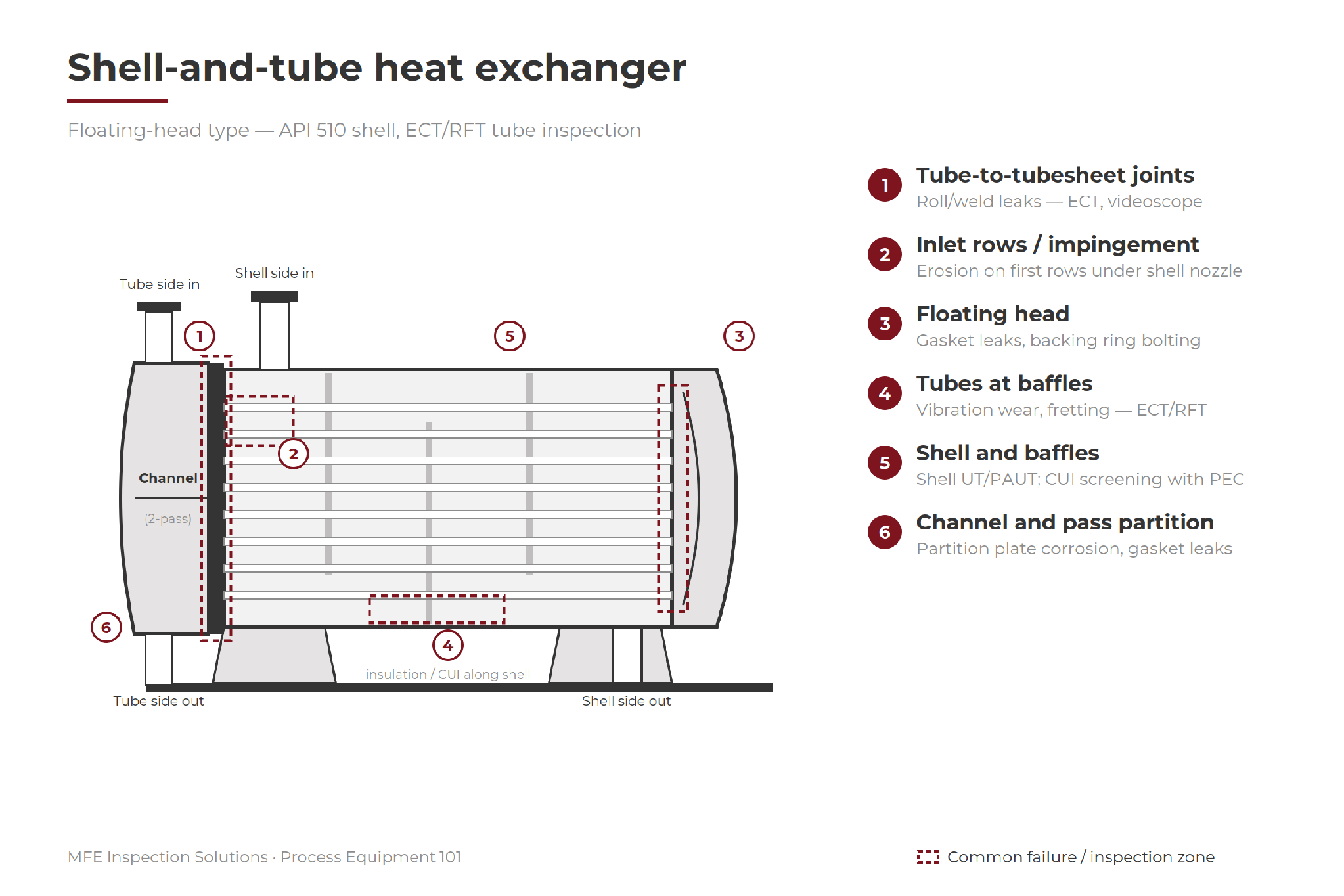
Original exchanger component and inspection-zone illustration. Use the exchanger’s actual tube map, pass arrangement and bundle design to locate observations and record unexamined regions.
Where it fails
Tube walls. Corrosion, pitting and localized thinning may originate on either surface. The tube material and expected damage determine which inspection techniques provide useful evidence. [2]
Tube-to-tubesheet joints. A leaking joint can permit fluid crossover even where the nearby tube wall appears sound. Joint condition and tube-wall condition require distinct attention.
Baffles and supports. Local wear and flow-induced vibration can damage tubes around support contacts. Examination coverage and interpretation should account for these regions.
Fouling and deposits. Deposits can reduce heat transfer, obstruct probes and conceal or contribute to corrosion. Cleaning condition affects what an examination can establish.
Shell and channel. Inlet regions, welds and insulated external surfaces have their own pressure-boundary inspection needs. Tube results do not replace assessment of the surrounding vessel.
U-bends and inaccessible lengths. Geometry and access can limit examination coverage. Record the actual inspected length of each tube and distinguish an inaccessible region from an acceptable result.
How it gets inspected
Define tube material, geometry and expected damage before selecting the technique. Coordinate cleaning, access, tube numbering and data review with the outage plan. Record examination coverage and confirm significant indications using methods appropriate to the suspected damage.
API 510 may apply to the exchanger’s pressure-containing components. The owner’s requirements, exchanger design and tube-inspection plan determine how tube findings are assessed and dispositioned. [1]
Equipment for the job
Select the method for the suspected damage, material, geometry and access, then choose a suitable instrument and configuration. These equipment examples support different parts of the job; no single tool establishes the condition of the entire asset.
Tube inspection. Eddyfi Ectane 2 with suitable probes and configuration supports tube examination. ECT is commonly used on non-ferromagnetic tubing, while RFT is used on ferromagnetic tubing such as carbon steel. IRIS ultrasonic inspection can assess tube wall thickness where cleaning, water coupling, and access permit. Select the technique for the tube material, geometry, and expected damage.
Tubesheets and ligaments. Eddyfi Reddy 64 with appropriate surface-array probes can support compatible crack examinations. Surface condition, material, and access determine coverage.
Shell thickness. Olympus 38DL Plus / Cygnus 1 Ex for suitable thickness measurements; HydroFORM corrosion mapping near inlet regions where surface curvature and access fit the scanner.
Channel and shell welds. OmniScan X4 with appropriate probes and scanners for PAUT. COBRA is suitable only where connection diameter and access fall within its operating envelope.
Tube ID visual. Evident IPLEX GT / MFE Series Videoscope for accessible tube interiors and fouling observations. Visual examination complements electromagnetic findings but does not replace wall-thickness assessment or independently clear indications.
CUI on the shell. MFE PulsePro / Eddyfi Lyft for screening compatible ferromagnetic walls through suitable insulation systems. Follow up suspect areas with an appropriate direct examination.
Materials. XRF / PMI analyzers help verify replacement tube alloys against the specified material; choose an analyzer appropriate to the elements that must be distinguished.
Leak observations in service. FLIR Si2-Pro may help locate accessible pressurized-gas leaks, and FLIR T540 may reveal thermal anomalies around connections. Neither provides a universal test for internal tube leakage or bypass; use a leak-testing plan suited to the service and accessible boundary.
Field note. The final deliverable should be a traceable tube map, not only a count of indications. Keep examined lengths, limitations, confirmation results and the approved tube dispositions together.
Why it matters
Tube integrity and thermal performance both affect reliable operation. Planning access, cleaning, tube identification, and examination coverage before the turnaround helps teams make repair, plugging, or replacement decisions within the available outage window.
Ask your inspection provider
How many bundles are in the next turnaround, which tube materials and damage mechanisms are involved, and how will inspection coverage and follow-up findings be recorded?
Field card - record on every route
Identify. Exchanger and bundle IDs, tube material, geometry, tube map and cleaning condition.
Record. Technique and probe configuration, tube numbers, examined length and signal/data references.
Confirm. Record characterization or supplementary testing for significant indications.
Flag gaps. Blocked tubes, inaccessible tube ends, U-bends, support regions and incomplete examination lengths.
Close the loop. Repair/plugging/replacement decisions, review authority and the final tube disposition map.
Support for the inspection
Coordinate cleaning, tube-end access, probe selection and calibration standards before the outage. Agree how significant indications will be reviewed and how plugging, repair or replacement decisions will be reflected on the final tube map.
Training, Repairs & Calibrations and Proof of Concept support are available through MFE Inspection Solutions.
Sources and equipment references
1. API - Pressure vessel inspection framework
2. Eddyfi - Tube inspection methods
3. Eddyfi - IRIS ultrasonic tube inspection
4. Eddyfi - Advanced tubing solution
This educational guide does not replace an asset-specific inspection procedure. The author is an executive at MFE Inspection Solutions. Equipment and service links lead to MFE; cited manufacturer information supports method selection. Confirm instrument suitability and availability for the planned scope.