 Inside the Asset
Illustrative inspection scene. The numbered anatomy reference below locates common components and inspection zones; actual equipment configurations vary.
What it is
An elevated flare receives relief and blowdown gas and burns it at a controlled location above grade. Pilots and purge systems support readiness during normal operation; upset and emergency flows may be much larger. It is one part of the plant relief system, not a substitute for individual pressure-relief devices.
This guide covers an elevated flare and its associated equipment. Inspection planning should distinguish the burner and pilots, riser and supports, and connected drums and header piping. Their operating conditions and access constraints are different.
How it works
Header. Relief and blowdown piping collects gas from connected equipment and routes it toward the flare system. Its service history and geometry determine the piping inspection scope.
Knockout drum. The drum separates entrained liquid before gas reaches the tip. Liquid handling and drum condition matter because liquid carryover can disrupt the intended flare operation.
Seals and purge. Seal arrangements limit air ingress or reverse flow according to the design. They do not remove the need to understand the specified purge and operating arrangements.
Riser and structure. The riser carries gas to the elevated tip. A self-supporting stack, guyed stack and derrick-supported flare have different structural components and observation routes.
Tip and pilots. Pilots provide ignition, while the tip distributes gas for combustion. Steam or air assist, where fitted, affects mixing and smoke; the actual burner configuration defines the inspection points. [1]
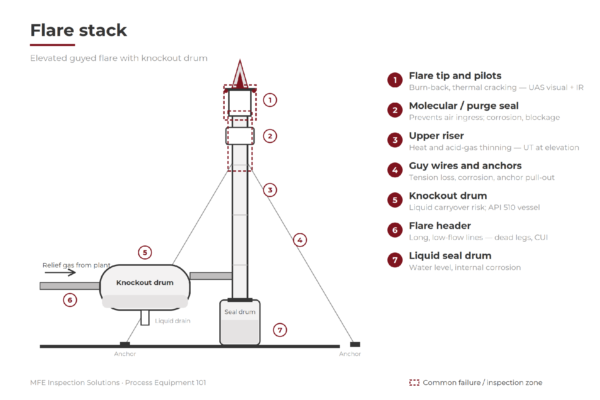
Original flare-system location reference. The stack, tip, supports, drums and header remain separate inspection scopes; actual access depends on the operating state and plant arrangement.
Where it fails
Tip and windshield. Heat exposure, cycling and local flame behavior can contribute to cracking, distortion or burn-back. Visible condition helps plan follow-up, but images cannot establish every hidden dimension.
Pilots and ignition. A failed pilot or damaged ignition component can compromise readiness. Correlate remote observations with the plant’s operating and pilot-monitoring records.
Riser. Corrosion and wall loss may develop at elevations or interfaces affected by the service and temperature. A visual survey cannot substitute for contact thickness measurements.
Guy wires, anchors and base. Corrosion, loose or damaged connections and foundation deterioration warrant structural follow-up. A camera view does not establish guy-wire tension or the integrity of concealed connections.
Connected drums and piping. Internal corrosion, liquid accumulation and insulation-related deterioration require their own examination plans. Do not count an aerial flare survey as inspection of these pressure boundaries.
How it gets inspected
Build separate scopes for the tip and pilots, riser and supports, and the connected drums and piping. Remote observations can guide maintenance planning. Contact measurements depend on surface access, temperature, coupling and equipment limits; an image alone does not establish remaining wall thickness.
Use distinct inspection scopes for the flare structure, pressure drums and piping. API 510 may apply to the drums, while API 570 and API 574 address applicable piping inspection and component practices. These references do not define a universal flare-stack inspection procedure. [3, 4]
Equipment for the job
Select the method for the suspected damage, material, geometry and access, then choose a suitable instrument and configuration. These equipment examples support different parts of the job; no single tool establishes the condition of the entire asset.
Tip, pilots and structure. Use a suitable zoom-imaging platform, such as DJI Matrice 350 RTK with a compatible H30-series payload; thermal imaging requires the thermal-capable variant. Confirm the exact platform/payload configuration before mobilization. Heat, plume, wind and guy-wire clearance determine the access plan.
Contact UT at elevation. Voliro T for suitable accessible riser surfaces; MFE HPX Wall Crawler for compatible ferromagnetic surfaces. Temperature limits, surface condition, coupling and site authorization determine whether in-service measurements are feasible.
Combustion and emissions. MFE OGI 640, MFE Detect LW or FLIR GF320 may support gas observations when the target gas matches the camera spectral response and survey conditions. OGI images alone do not quantify flare destruction efficiency or demonstrate emissions compliance.
Knockout and seal drums (API 510). Olympus 38DL Plus / Cygnus 1 Ex for thickness; Elios 3 for internals at turnaround
Flare header piping. MFE PulsePro for CUI on insulated runs; MFE PipeScan MFL on bare pipe
Structural. visual on guy wires, anchors, and base bolting — drone or ground
Field note. A close image, a thermal observation and a contact thickness reading answer different questions. Record which evidence supports each finding, and list any areas hidden by plume, geometry or access restrictions.
Why it matters
Flare readiness matters most during an upset. Remote surveys can reveal tip, pilot and structural problems while helping teams plan the access and outage work that still needs direct examination.
Ask your inspection provider
What standoff and temperature limits apply, and which findings will require contact measurements or an outage?
Field card - record on every route
Identify. Flare ID, tip/pilot arrangement, riser design, supports and linked drum/piping IDs.
Record. Operating condition, observation position, weather, visible/thermal findings and image references.
Confirm. Separate gas observations, visual condition and contact thickness results; record the purpose of each method.
Flag gaps. Plume-obscured areas, inaccessible surfaces, temperature restrictions and unexamined structural connections.
Close the loop. Outage or contact follow-up, maintenance priority, assigned owner and completion evidence.
Support for the inspection
Coordinate the inspection with operations and the flare-system owner. Review the access route, operating restrictions, instrument temperature limits and the work that must wait for an outage. Agree how findings will be assigned to maintenance or structural specialists.
Training, Repairs & Calibrations and Proof of Concept support are available through MFE Inspection Solutions.
Sources and equipment references
1. Zeeco - Flare systems and supporting equipment
2. Voliro - High-temperature UT payload application
3. API - Pressure vessel inspection framework
4. API - Piping inspection and component practices
This educational guide does not replace an asset-specific inspection procedure. The author is an executive at MFE Inspection Solutions. Equipment and service links lead to MFE; cited manufacturer information supports method selection. Confirm instrument suitability and availability for the planned scope.