 Inside the Asset
Noncontact thermal inspection of compressor cylinder and valve-cover surfaces. AI-generated illustration; instrument appearance and geometry are illustrative.
What it is
A reciprocating compressor raises gas pressure by moving a piston within a cylinder. Suction and discharge valves admit and release gas as cylinder pressure changes. In upstream and midstream facilities, these machines support duties such as gathering and gas transport.
This guide illustrates a horizontal crosshead process-gas compressor. Cylinder arrangements, stages, unloading systems and lubrication designs vary. The frame, cylinder and rod-packing system need their own inspection locations; the driver and connected pressure equipment also need defined scopes. [1, 2]
How it works
Cylinder and valves. The piston changes the available gas volume. Suction and discharge valves operate with the pressure difference across them; their condition influences the gas path and performance.
Rod and packing. The piston rod transmits force between the piston and crosshead. Packing controls gas leakage along the moving rod. Rod condition, packing arrangement and any cooling or lubrication provisions must be considered together. [1, 3]
Crosshead and crankcase. The crankshaft and connecting rod convert rotation into reciprocating motion. The crosshead guides the rod, while bearings and lubrication support the running gear.
Piping and package. Pulsation-control equipment, piping supports, coolers and the foundation form part of the package. Their behavior depends on the actual operating configuration; the diagram does not define a pressure or pulsation design.
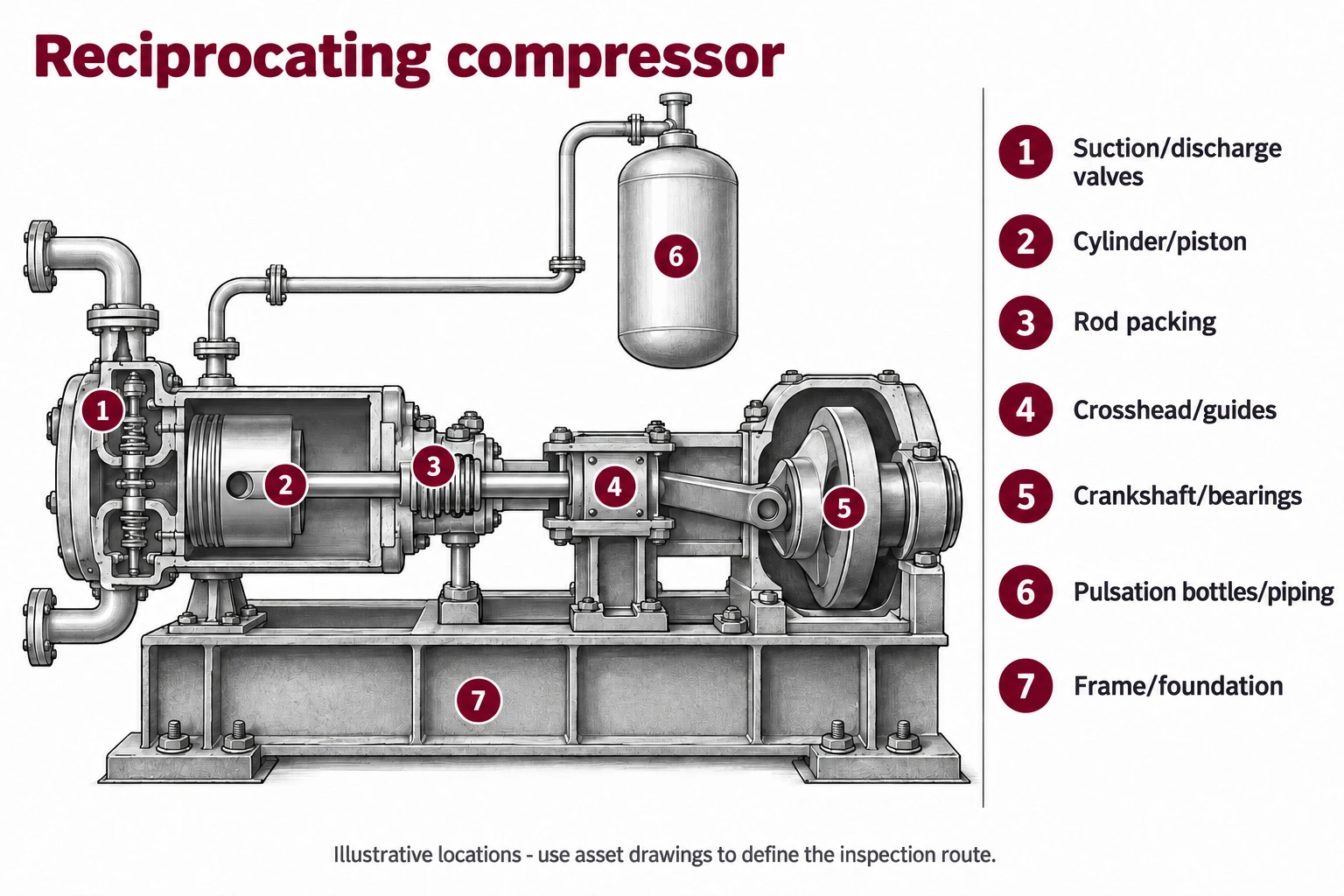
AI-generated component-location illustration, not to scale. Use the asset’s drawings and identifiers to localize findings; highlighted zones illustrate component areas and do not define complete examination coverage.
Where it fails
Valves and cylinder. Wear, deposits or damaged components can affect performance. An unusual external temperature pattern can prompt investigation, but it is not a universal valve diagnosis or a measure of cylinder internal condition.
Rod and packing. Rod wear and packing deterioration can affect leakage. A visible leak observation must be tied to its location and operating condition, distinguishing intended vent arrangements from a finding requiring action. [1, 2]
Guides, bearings and lubrication. Wear, contamination or lubrication problems can affect the running gear. Check the relevant frame and cylinder/packing lubrication arrangements rather than assuming they share one system. [4]
Piping, frame and foundation. Fatigue, looseness, deteriorated supports or abnormal movement warrant specialist follow-up. Compressor vibration and piping pulsation are related operating concerns, but they are not interchangeable measurements.
How it gets inspected
Build the route around the compressor frame, cylinder and stage IDs. Record speed, load or unloading configuration, suction/discharge conditions and relevant gas service. Compare like operating states and retain the exact valve or packing location for repeat observations.
Separate performance diagnostics, gas-leak observations, pressure-boundary examinations and mechanical condition assessment. Plan internal access under the owner’s machine-specific isolation and maintenance procedure. The inspection report should explain what each technique assessed and which components still need direct examination.
Equipment for the job
Choose the method for the question, then the instrument and configuration for the asset. The following options address different parts of the inspection.
Thermal and visual survey. A suitable thermal camera and zoom imaging can document accessible valve-cap, cylinder and package conditions. Record load, pressure conditions and viewing geometry. Compare repeatable positions; emissivity, shielding and internal gas conditions can complicate interpretation. A FLIR T540 is an example for this surface-temperature survey.
Performance diagnostics. A qualified compressor specialist may use suitable cylinder-pressure, crank-angle and operating data to investigate performance or valve behavior. Instrumentation and interpretation must fit the machine. An external photograph cannot replace this work when internal performance is the question.
Vibration and mechanical assessment. Use an analyzer and sensors suited to reciprocating machinery, together with the operating state. The measurement locations and analysis differ from simply applying a rotating-machine alarm value. Suspected support or pulsation issues may require a separate package/piping assessment.
Gas-leak localization. A gas-compatible OGI camera or suitable acoustic leak instrument may support observations at accessible connections and packing-related locations. Match the method to the target gas and survey conditions. Neither absence of an image nor an acoustic indication alone establishes complete leak tightness. [2] For compatible hydrocarbon service, a FLIR GF320 is an OGI option; select it for the actual gas and viewing conditions.
Internal inspection. Use direct inspection or a suitable videoscope during prepared access to document reachable cylinder, piston and valve features. Record orientation and access limits. Close images complement, but do not replace, the required dimensional or component-specific checks. An Evident IPLEX GT is an option when probe access suits the component.
Lubrication and targeted NDT. Repeatable oil sampling can support frame-condition assessment. Appropriate surface, ultrasonic or other examinations may be selected for suspected component or pressure-boundary damage. Keep cylinder/packing lubrication requirements separate where the package uses a different supply. [4]
Field note
A compressor route should identify the operating configuration as carefully as the component location. Without both, a changed signal may be difficult to compare or interpret.
Why it matters
Compressor reliability depends on more than the cylinder. A valve, packing, support or running-gear problem can reduce performance or interrupt gas movement. Coordinated diagnostics help the owner direct maintenance toward the affected function and track whether the action resolved the finding.
Ask your inspection provider
How will you distinguish a valve or gas-path issue from packing leakage, running-gear condition and piping/support behavior, and what operating data do you need to do that?
Field card - record on every route
Identify. Frame, cylinder, stage and valve references; packing/vent locations and connected equipment IDs.
Record. Speed, load/unloading state, pressures, relevant temperatures, method and exact observation position.
Confirm. Match significant observations to performance, mechanical, leakage or pressure-boundary follow-up.
Flag gaps. Hidden components, inaccessible vents, incomplete operating data and pressure parts outside the survey.
Close the loop. Finding, required specialist review, responsible person, disposition and post-maintenance comparison.
Support for the inspection
Coordinate with the owner and compressor specialists before selecting the diagnostic scope. Confirm gas compatibility and site suitability for instruments. MFE can support appropriate imaging and NDT tools; performance analysis, pulsation studies and repair acceptance require the relevant expertise.
Sources and equipment references
1. Ariel - Piston-rod loading and wear regions
2. Ariel - Compressor leakage locations
3. Ariel - Packing cooling considerations
4. Ariel - Cylinder and packing oil supply
5. Ariel - Reciprocating compressor theory
Educational guide by Jason Acerbi, an executive at MFE Inspection Solutions. These guides do not replace asset-specific procedures or engineering assessment. Named instruments are examples, not a claim that MFE supplies every diagnostic service or stocks every configuration. Confirm suitability and availability for the planned task.