 Inside the Asset
Illustrative inspection scene. The numbered anatomy reference below locates common components and inspection zones; actual equipment configurations vary.
What it is
Pipe, fittings, flanges, valves and supports carry process fluids between vessels, exchangers, pumps and tanks. A plant may contain many circuits with different materials, temperatures, pressures and damage mechanisms.
This guide focuses on process piping within industrial facilities. It does not treat every transmission pipeline, buried utility or drain as the same asset. Organize the work by circuit, material, service and credible damage mechanism.
How it works
Pipe and fittings. Straight runs, elbows, tees and reducers carry fluid and change its direction or velocity. Material selection and wall thickness depend on the service and design.
Joints and valves. Welded, flanged and other qualified joints connect components; valves control or isolate flow. Flange integrity depends on the gasket, fasteners, assembly and operating conditions.
Supports and movement. Shoes, hangers, guides and anchors carry weight and control movement. Restraint and thermal expansion must work as intended to avoid unwanted loads on piping and equipment nozzles.
Insulation and weather protection. Insulation supports temperature control and personnel protection. Damaged weather barriers can admit water and create corrosion conditions at concealed surfaces.
Dead legs and branches. Low-flow or no-flow sections can accumulate water or solids. Small-bore branches also introduce locations where vibration and local stresses deserve attention.
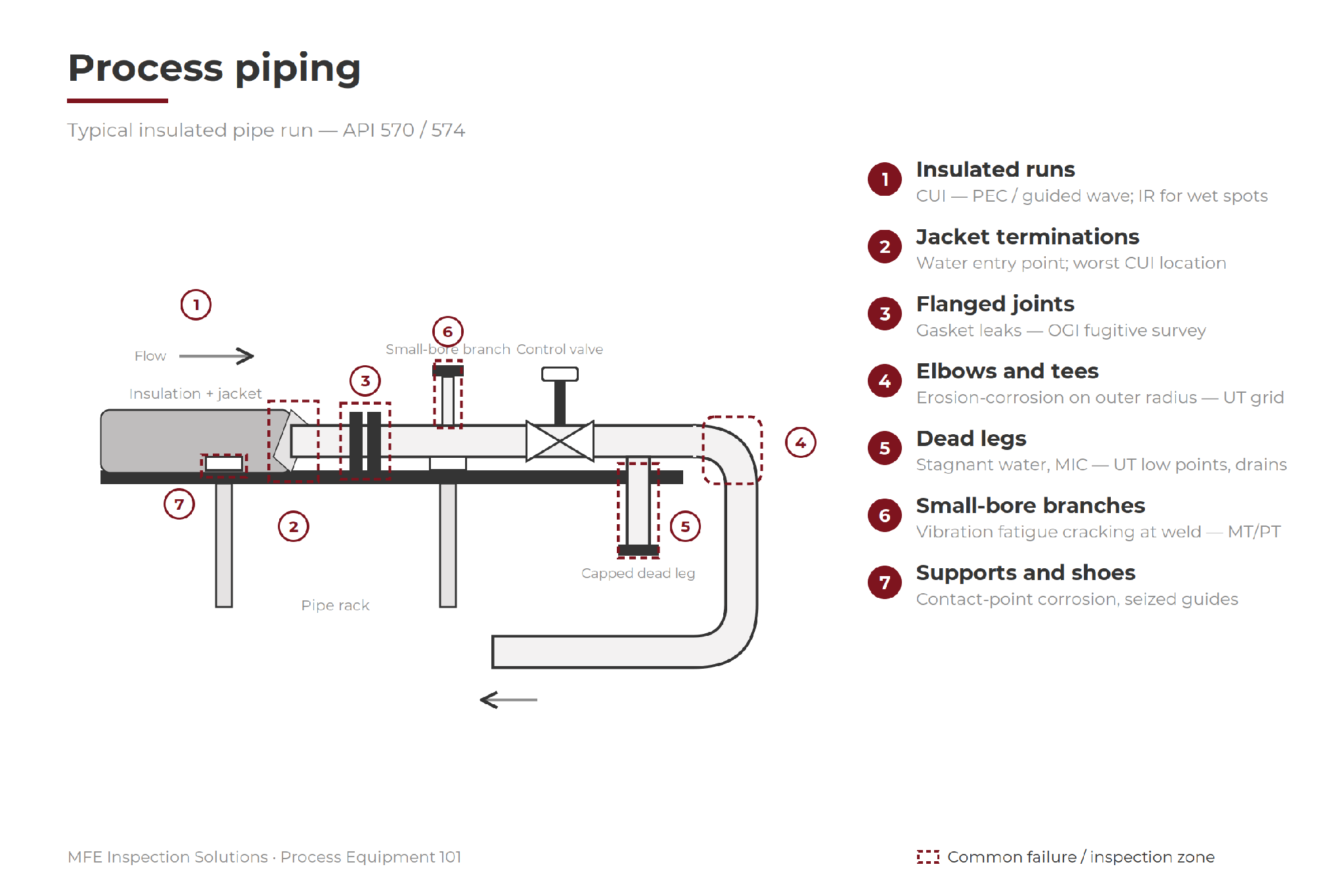
Original process-piping inspection-zone illustration. Confirm circuit limits and identify each fitting, support and branch on the facility drawings before assigning examination locations.
Where it fails
Insulated lengths. Corrosion under insulation can remain hidden beneath apparently intact jacketing. Moisture-entry points, low areas and damaged weather barriers help focus examination, but local condition must be established. [2]
Elbows, tees and valve outlets. Erosion-corrosion and other flow-related damage can concentrate where flow changes. Record the orientation of the reading, not simply the fitting name.
Dead legs and low points. Stagnant contents, deposits and service chemistry can create localized internal attack, including microbiologically influenced corrosion in susceptible conditions.
Flanged joints. Leakage can follow gasket, bolt-load or thermal-cycle problems. A gas observation identifies a finding to investigate; it does not by itself determine the joint repair scope.
Supports and small-bore connections. Corroded shoes, seized guides, damaged attachment welds and vibration-related branch cracking can threaten reliability even when the main run has acceptable thickness.
How it gets inspected
Organize the route by piping circuit and damage mechanism. Use repeatable examination locations and traceable readings. Screening can prioritize suspect areas, but local confirmation and consistent recording are what make the data useful for trending and repair planning.
API 570 addresses in-service inspection, rating, repair and alteration of applicable piping systems. API 574 provides companion inspection practices for piping components. The circuit’s service and governing requirements determine the actual plan. [1]
Equipment for the job
Select the method for the suspected damage, material, geometry and access, then choose a suitable instrument and configuration. These equipment examples support different parts of the job; no single tool establishes the condition of the entire asset.
CUI screening. MFE PulsePro or Eddyfi Lyft PEC can screen compatible ferromagnetic pipe through suitable insulation and jacketing. The probe still needs physical access to the insulation surface; readings average a footprint and may miss small local pits. FLIR E96 thermal anomalies can help prioritize follow-up, but do not establish wall thickness.
Thickness at elbows, tees and dead legs. Olympus 38DL Plus, 45MG, Danatronics ECHO 9 or Cygnus 1 Ex; HydroFORM mapping where curvature and probe access are suitable; MFE PipeScan MFL on compatible bare ferromagnetic pipe. Confirm screening indications with suitable UT.
Welds and small-bore branches. OmniScan X4 with COBRA where diameter and geometry fit; Eddyfi Sharck / Reddy 64 for compatible surface-crack applications. Material, coating and branch geometry determine the method and probe.
Flanges and fugitive emissions. MFE Detect MW OGI Camera, FLIR GF320 or GF77 with the correct gas-sensitive configuration; FLIR Si2-Pro / CRYSOUND 8124 acoustic imaging for suitable pressurized-gas and steam leak surveys.
Pipe racks and elevated runs. DJI Matrice 350 RTK with a compatible Zenmuse H30-series payload; MFE OGI 640 for compatible gas surveys; Boston Dynamics Spot with MFE Spot Connect Gas Detection for repeatable rounds where route and hazardous-area requirements permit.
Large-diameter and buried lines. Deep Trekker DT340 / Pipe Trekker A-200 crawlers for accessible suitable pipe interiors; Wöhler VIS 700 for suitable drains; MALÅ GPR Easy Locator can help locate buried services, subject to soil conditions, depth and target detectability.
Coatings. Tinker & Rasor holiday testers; DeFelsko PosiTector 6000 coating thickness
Field note. Keep screening results, direct confirmation and follow-up actions attached to the same circuit and location reference. A reading without a repeatable location is difficult to trend or use for repair planning.
Why it matters
Piping integrity depends on repeatable monitoring across many circuits. Consistent locations, traceable readings and follow-up of screening results make each survey useful for the next maintenance decision.
Ask your inspection provider
How are circuits and examination locations selected, and how will screening findings be confirmed and trended?
Field card - record on every route
Identify. Circuit and line IDs, service, material, insulation system and examination locations.
Record. Location references, screening footprint, instrument configuration, readings and comparison with prior results.
Confirm. Link each suspect screening area to direct examination and the resulting disposition.
Flag gaps. Dead legs, supports, elbows, branches, insulation-access restrictions and unexamined lengths.
Close the loop. Follow-up action, responsible person, due date and the record used for future trending.
Support for the inspection
Agree circuit boundaries, location naming and repeatable measurement positions before mobilization. Review probe access, insulation condition and the planned confirmation of screening results with the provider.
Training, Repairs & Calibrations and Proof of Concept support are available through MFE Inspection Solutions.
Sources and equipment references
1. API - Piping inspection and component practices
2. Eddyfi - Pulsed eddy current and probe footprint
3. Eddyfi - PEC on small-diameter pipes
This educational guide does not replace an asset-specific inspection procedure. The author is an executive at MFE Inspection Solutions. Equipment and service links lead to MFE; cited manufacturer information supports method selection. Confirm instrument suitability and availability for the planned scope.