 Inside the Asset
AI-generated inspection illustration. Equipment arrangement and camera display are illustrative. Actual surveys require an unobstructed view of the target and site-approved observation positions.
What it is
A substation is a collection of electrical assets that switches circuits, protects the power system and, where transformers are installed, changes voltage. It connects generating plants, transmission lines, distribution networks or large industrial loads. A switching station can perform its role without changing voltage. [1]
This guide focuses on a typical outdoor air-insulated substation. Gas-insulated and indoor installations need different access and inspection arrangements. The inspection scope includes the transformer, switching equipment and the protection systems that make them work together.
How it works
Incoming and outgoing circuits. Lines and cables connect the substation to the network or facility. Busbars provide common connection points; the actual bus arrangement determines operating flexibility. [1]
Power transformer. Where fitted, it transfers energy between windings at different voltage levels. Bushings carry connections through the grounded tank; cooling equipment removes heat. [1, 5]
Circuit breakers and disconnects. Breakers interrupt rated load and fault currents. Disconnectors establish isolation under their specified duties; they are not interchangeable with fault-interrupting breakers. [1, 6]
Insulation and surge protection. Insulators support live conductors, while surge arresters limit overvoltage stress. Condition and contamination affect the insulation system. [1, 3]
Measurement, protection and control. Instrument transformers supply measurement signals. Relays evaluate electrical conditions and command breakers; station batteries and DC circuits support protection and control. [1, 6]
Grounding and civil works. Grounding, foundations, drainage, containment and access arrangements are part of the asset, alongside the electrical equipment. [1, 2]
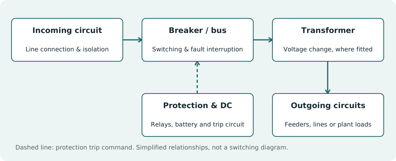
Component overview: actual substations may contain multiple buses, transformers, breakers and alternate power paths. Use the facility drawings to define the inspection route.
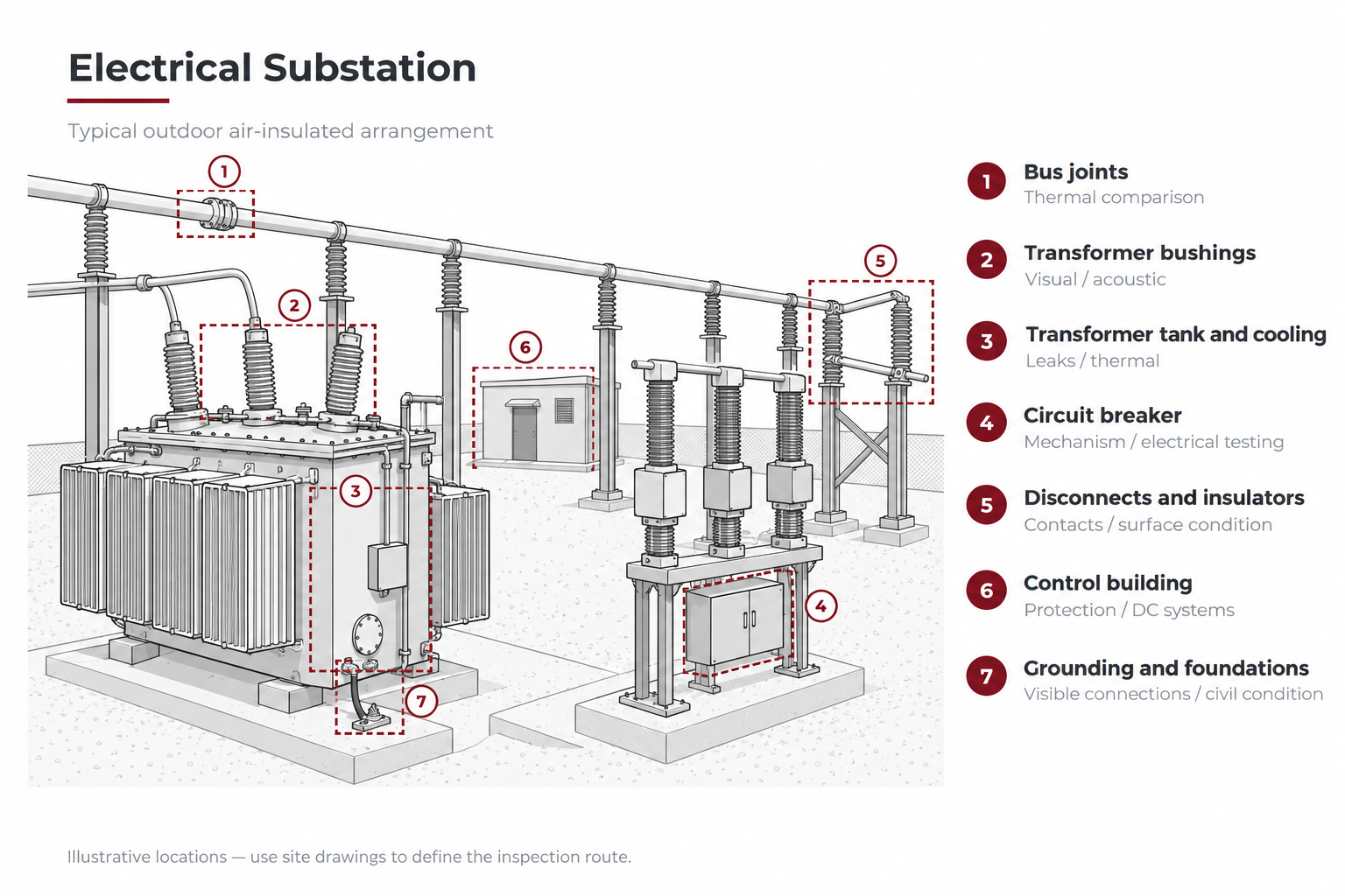
Numbered inspection-location reference: 1 bus joints; 2 transformer bushings; 3 transformer tank and cooling; 4 circuit breaker; 5 disconnects and insulators; 6 control building; 7 grounding and foundations. The illustration locates common points of interest; use site drawings and equipment IDs to define the actual route.
Where it fails
Connections and contacts. Poor connections can develop elevated resistance and heating. A thermal anomaly is a reason to investigate; it does not, by itself, identify the defect or establish repair scope. [4, 6]
Insulators, bushings and terminations. Cracks, contamination and insulation deterioration can be associated with discharge activity. Airborne acoustic detection depends on whether a signal can reach the sensor. [3]
Transformer insulation and cooling. Oil leaks, moisture, cooling problems and electrical or thermal faults require different diagnostic approaches. Dissolved gas analysis and other tests help assess conditions hidden from an external camera. [5]
Breaker mechanisms and control circuits. A breaker can look normal but fail to operate as intended. Timing, mechanism condition and the protection/control chain require dedicated testing. [6]
Gas-insulated equipment, where installed. Leaks or abnormal gas condition can affect equipment performance. Identify the insulating medium before choosing a detection method; not every installation uses SF6. [7]
Supporting infrastructure. Deteriorated grounding connections, corroded structures and water ingress warrant follow-up. An external visual survey cannot establish the condition of buried grounding or all concealed parts. [1, 2]
How it gets inspected
Build the route around equipment IDs, operating condition and failure mechanisms. Separate observations made with equipment energized from tests that require a planned outage. Combine thermal and acoustic findings with operating records, prior results and equipment-specific diagnostic tests. [3-6]
The owner's electrical maintenance program, OEM guidance and applicable requirements determine the scope. In the United States, OSHA 29 CFR 1910.269 addresses covered electric-power work; applicability depends on the work and installation. Qualified personnel, approach distances and site controls remain essential even when cameras are used. [2]
Equipment for the job
Select the inspection method first, then the equipment that can answer the question. The examples below are options, not a complete electrical test package.
Thermal survey - connections, bushings and cooling. FLIR T540 is one handheld option. Choose suitable optics and viewing positions. Record load and environmental conditions; emissivity and reflections can distort apparent temperature. Thermal imaging observes accessible surfaces, not the internal condition of every component. [4, 8]
Acoustic survey - accessible discharge activity. FLIR Si2-Pro supports partial-discharge surveys. Confirm electrical-discharge capability in the selected model. Noise, obstructions and the discharge location affect detection; an absence of detected sound does not clear the insulation system. [3, 9]
Visual survey - condition and access. Use suitable zoom imaging to document visible damage, leaks and deterioration from authorized positions. A drone is an access option only after the owner evaluates electrical clearances, structures and flight constraints; remote viewing does not authorize closer approach. [1, 2]
Transformer diagnostics - internal condition. A qualified provider may combine oil sampling/DGA, moisture assessment and appropriate electrical tests. Select the tests for the transformer design, history and findings. External thermal or acoustic screening does not replace this work. [5]
Breaker and protection testing - operation. Suitable breaker analyzers, contact-resistance instruments and protection test equipment address different functions. The test plan must specify isolation, test configuration and acceptance criteria; coordinate this work with the owner's electrical specialists. [6]
SF6 leak detection - only where applicable. FLIR G306 is an SF6-specific OGI example. Select a detector for the actual gas and conditions. A hydrocarbon OGI camera should not be assumed to detect SF6, and leak imaging does not establish gas quality or insulation health. [7]
Field note: A camera finding is an observation to document, interpret and follow up. A complete assessment combines the appropriate inspection methods with operating context and targeted tests.
Why it matters
Substation reliability depends on more than the largest transformer. A connection, breaker mechanism or control-system problem can interrupt supply to a wider facility. A repeatable inspection route helps turn visible symptoms into traceable findings, targeted tests and planned maintenance.
Ask your inspection provider
Which assets and failure mechanisms will this survey cover, what will remain unexamined, and what tests will confirm significant findings before maintenance decisions are made?
Field card - record on every route
Asset ID and phase; location and viewing position; equipment operating state and load; environmental conditions; method and instrument configuration; image or test reference; finding and comparison with prior results; areas not examined; required follow-up and responsible person.
Support for the inspection
Method-specific training, instrument calibration and an access review help prepare the inspection team. Coordinate electrical testing with qualified personnel and the owner's maintenance program.
Sources and equipment references
1. OSHA - Substation components
2. OSHA - Electric power work and minimum approach distances
3. FLIR - Acoustic imaging for partial-discharge monitoring
4. FLIR - Substation thermal monitoring / emissivity
5. Hitachi Energy - Transformer inspection and diagnostics
6. Megger - High-voltage circuit-breaker diagnostic testing
7. FLIR - G306 SF6 optical gas imaging camera
8. FLIR - T540 thermal camera; temperature interpretation
9. FLIR - Si2-Pro electrical-discharge capability
Additional: FLIR - How emissivity affects thermal imaging
This educational guide does not replace an asset-specific inspection procedure. The author is an executive at MFE Inspection Solutions. MFE equipment links lead to MFE; manufacturer references support method selection and do not imply MFE stocks every listed instrument.