 Inside the Asset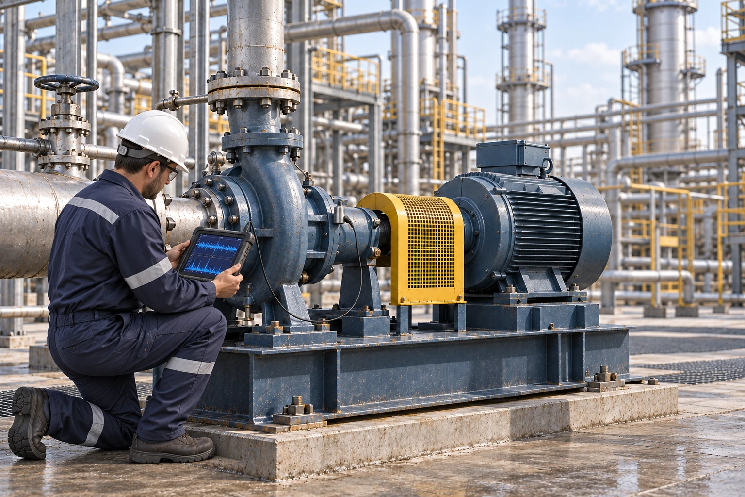
Vibration analysis using an accelerometer mounted on the pump bearing housing. AI-generated illustration; instrument appearance and geometry are illustrative.
What it is
A centrifugal pump uses a rotating impeller to transfer mechanical energy to a liquid. The casing collects and directs the flow toward the discharge. Process transfer, cooling-water and many utility duties use centrifugal pumps, with the design selected for the fluid and operating conditions. [1]
This guide illustrates a horizontal, end-suction pump. Multistage, vertical, between-bearings and sealless designs need different component maps. Inspect the pump as part of its system: suction conditions, piping, driver and operating point can matter as much as the visible casing.
How it works
Suction and impeller. Liquid enters the impeller eye and gains energy as it travels through the rotating passages. The actual flow depends on the pump and connected system, not simply on the motor rating. [1]
Casing and discharge. The casing guides liquid from the impeller toward the outlet. Nozzles and joints contain the fluid while connected piping can impose loads on the pump.
Seal and shaft. Where fitted, a mechanical seal or packing controls leakage around the shaft. Seal-support arrangements vary with the design and service; inspect the supporting lines and conditions as well as the visible seal area. [2]
Bearings, coupling and base. Bearings support the shaft, the coupling connects the driver, and the base transfers load to the foundation. Lubrication, alignment and fastening are part of the operating condition of the assembled train. [3]
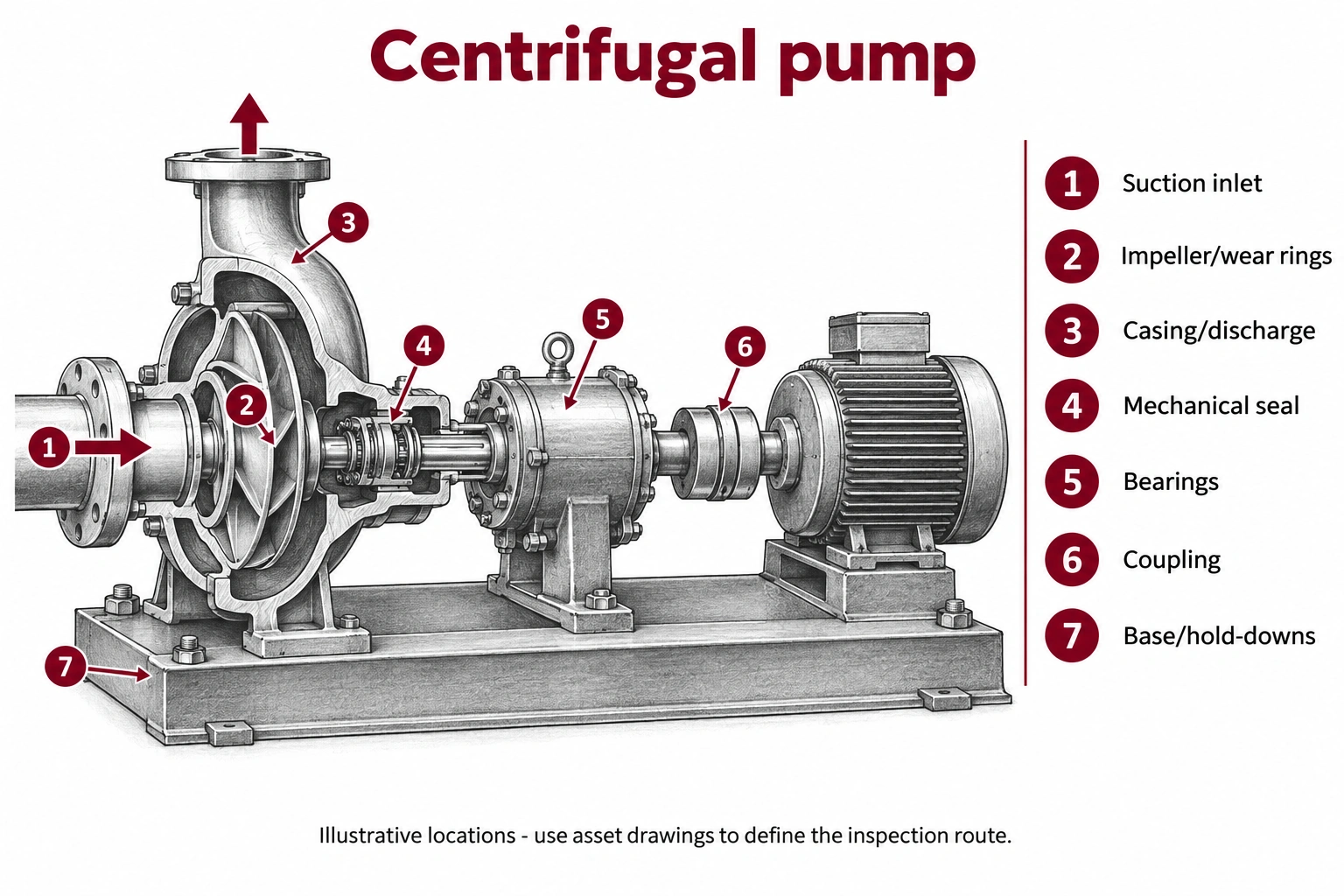
AI-generated component-location illustration, not to scale. Use the asset’s drawings and identifiers to localize findings; highlighted zones illustrate component areas and do not define complete examination coverage.
Where it fails
Suction conditions and cavitation. Vapor cavities can form and collapse when local pressure conditions permit. Noise, vibration, performance loss or surface damage may be associated with cavitation, but sound alone does not prove the cause. Investigate the hydraulic conditions. [4]
Impeller, wear regions and casing. Erosion, corrosion, deposits or damaged surfaces can affect performance and containment. Localize observations to the impeller passage, wear region or casing location instead of reporting only that the pump is worn.
Seal and support system. Leakage may involve worn faces, inadequate support conditions, shaft movement or other factors. Repeated seal replacement without checking the operating context can leave the cause unresolved. [2, 3]
Bearings, alignment and foundation. Abnormal vibration, temperature, looseness or support movement warrants follow-up. Similar symptoms can have different causes; assess the pump, coupling, driver and connected piping as a system. [3]
How it gets inspected
Record the pump ID, duty, operating speed, flow and suction/discharge conditions where available. Compare observations at repeatable locations and under comparable operating conditions. A trend collected at different duties may describe a process change rather than progressive mechanical damage.
Combine operating measurements, external observations and internal inspection during planned access. Keep performance assessment, crack detection, wall-thickness measurements and alignment checks distinct. The owner’s maintenance program and the pump-specific instructions define the examination and disposition.
Equipment for the job
Choose the method for the question, then the instrument and configuration for the asset. The following options address different parts of the inspection.
Vibration analysis. A suitable portable analyzer and sensors can support repeatable bearing-housing measurements and diagnosis. Record sensor position and direction, speed and duty. Interpretation may require spectra, waveforms or other analysis beyond an overall value. Follow-up should address the actual suspected mechanism. [3]
Hydraulic measurements. Appropriate pressure, flow, temperature and power data help place the observation on the pump’s operating context. Review instrument condition and the applicable pump/system information. A vibration or acoustic finding should not be labeled cavitation without examining the supporting hydraulic evidence. [4]
Thermal comparison. A thermal camera can help compare accessible bearing housings, seal-support components and the driver. Record duty and viewing conditions. An elevated apparent temperature is a reason to investigate, not a stand-alone diagnosis of lubrication failure or bearing damage. A FLIR T540 is one option for these thermal comparisons.
Visual and remote visual inspection. Use suitable close-up imaging or a videoscope to document accessible impeller and casing surfaces when the pump is prepared for internal examination. Identify passage and orientation. Photographs of reachable areas do not clear hidden surfaces or establish internal dimensions. An Evident IPLEX GT can support inspection through suitable prepared access.
Alignment and mechanical checks. Appropriate alignment instruments and mechanical measurements help assess coupling alignment, fastening and support condition. Qualified personnel should use the machine-specific procedure. Keep these results separate from observations taken with the coupling guard installed during normal rounds. [3]
Leakage and targeted NDT. Document liquid leaks directly and use suitable examinations for suspected casing or weld damage. UT, surface-crack testing and dimensional checks answer different questions. Acoustic gas-leak detection is not a universal method for liquid leakage or pump internal condition.
Field note
Label every result with duty and location. The most useful report connects the symptom to the follow-up needed to distinguish a hydraulic problem from a mechanical one.
Why it matters
A pump can continue running while losing efficiency or developing a problem in the seal, bearings or suction system. A repeatable route helps identify changes early and supports a repair that addresses the cause instead of only replacing the most visible failed part.
Ask your inspection provider
How will you distinguish operating-point or suction problems from bearing, alignment and seal problems, and what evidence will support that diagnosis?
Field card - record on every route
Identify. Pump and driver IDs, design, fluid/service, component map and previous maintenance.
Record. Speed, duty, flow/pressure where available, sensor position/direction and image or test reference.
Confirm. Connect abnormal noise, heat, vibration or leakage to an appropriate diagnostic check.
Flag gaps. Unknown duty, inaccessible internal surfaces, missing baseline and measurements that are not comparable.
Close the loop. Cause under investigation, action, owner, post-maintenance verification and updated baseline.
Support for the inspection
Agree measurement positions and operating information before establishing a route. Confirm access for internal examination and specialist alignment or hydraulic review. MFE can assist with suitable visual, thermal and NDT instruments and training; the complete pump assessment may require additional diagnostic equipment.
Sources and equipment references
Educational guide by Jason Acerbi, an executive at MFE Inspection Solutions. These guides do not replace asset-specific procedures or engineering assessment. Named instruments are examples, not a claim that MFE supplies every diagnostic service or stocks every configuration. Confirm suitability and availability for the planned task.